How Are RS-485 to Ethernet Converters Used in Environmental Monitoring Systems
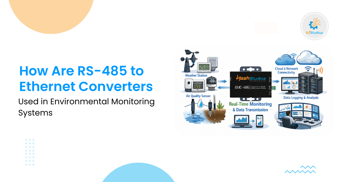
Environmental monitoring systems gather critical data on air quality, water quality, soil conditions, and climate variables to support public health, agriculture, and disaster prevention. Globally, air pollution affects over 90%