From Gateway to Dashboard Building an End-to-End Monitoring System

From Gateway to Dashboard: Building an End-to-End Monitoring System

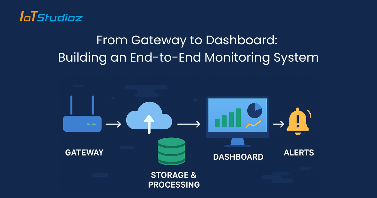
Modern businesses and industries run on data. From factories monitoring machine health to IT teams tracking server performance, real-time visibility is no longer optional; it’s essential. An end-to-end monitoring system ensures that data flows seamlessly from devices and gateways to the final dashboards where decision-makers can act.

But building such a system is not simple. It requires careful integration of hardware, communication protocols, cloud systems, databases, and visualization platforms. Done correctly, it helps organizations detect anomalies, improve efficiency, prevent downtime, and gain valuable insights.

1. Understanding the Concept of End-to-End Monitoring

End-to-end monitoring means tracking the entire data lifecycle from the moment data is generated to the point where it drives business action.

  • Data Origin: Sensors, devices, or applications generate raw information (temperature, pressure, CPU usage, network traffic, etc.).
  • Data Collection: Gateways collect and preprocess information before sending it further.
  • Transmission: Data moves securely via protocols (MQTT, HTTPS, LoRaWAN).
  • Storage and Processing: Systems organize and process data for analysis.
  • Visualization: Dashboards display insights in user-friendly formats.

The goal is to eliminate blind spots and create a transparent system where every stakeholder from technicians to executives can monitor performance.

2. The Role of IoT Gateways

Gateways are the first checkpoint in monitoring systems. They connect physical devices to digital networks and manage data flow.

Key functions of gateways include:

  • Protocol Translation: Converting legacy or industry-specific protocols (like Modbus, Zigbee, BACnet) into internet-ready formats (MQTT, HTTP).
  • Data Filtering: Removing unnecessary or duplicate information to save bandwidth.
  • Edge Processing: Performing calculations locally (e.g., detecting a machine anomaly) before sending data to the cloud.
  • Data Buffering: Storing data temporarily during network outages to prevent loss.
  • Device Management: Enabling remote configuration and firmware updates for connected devices.

Example: In a smart factory, a gateway collects temperature readings from multiple sensors, filters noise, and sends only relevant trends to the cloud reducing latency and bandwidth costs.

3. Data Transmission and Security

Once gateways process data, the next step is secure and reliable transmission to storage or cloud platforms.

  • Protocols:
    • MQTT for lightweight IoT communication
    • CoAP for constrained devices
    • HTTPS/WebSockets for cloud applications
  • Encryption: SSL/TLS ensures data cannot be intercepted or modified during transmission.
  • Redundancy: Secondary communication paths prevent downtime during network failures.
  • Scalability: Systems must handle thousands of devices without bottlenecks.

Without strong transmission mechanisms, monitoring systems risk delays, data loss, or even cyberattacks that could cripple operations.

4. Data Storage and Processing Layer

Raw data is only valuable when structured and analyzed. The storage layer ensures information is organized, retrievable, and ready for real-time and historical analysis.

  • Time-Series Databases: (e.g., InfluxDB, TimescaleDB) store metrics with timestamps for continuous monitoring.
  • Data Warehouses & Lakes: (e.g., Snowflake, AWS Redshift, Azure Data Lake) keep large-scale historical data for reporting and analytics.
  • Stream Processing: Kafka, Apache Flink, or Spark process events in real-time for instant alerts.
  • Normalization & Aggregation: Ensures data is standardized, reducing inconsistencies.

Example: In logistics, a fleet monitoring system aggregates fuel consumption, driver behavior, and GPS data to optimize routes and reduce costs.

5. Building the Dashboard

The dashboard is the user-facing layer of monitoring systems, the point where data turns into actionable insights.

A good dashboard should provide:

  • Real-Time Visualization: Graphs, charts, and maps that update instantly.
  • Custom Views: Role-based dashboards for technicians, managers, and executives.
  • Drill-Down Analysis: Ability to move from high-level KPIs to detailed logs.
  • Alert Management: Highlighting anomalies and sending notifications.
  • Cross-Device Accessibility: Web, desktop, and mobile support.

Tools like Grafana, Power BI, Kibana, or custom web apps are commonly used. A well-designed dashboard prevents information overload and keeps focus on what truly matters.

6. Challenges in Building an End-to-End Monitoring System

Creating a complete monitoring solution is complex, with several challenges:

  • Data Silos: Different systems may not communicate, causing fragmented views.
  • Scalability Issues: Adding more devices may overwhelm infrastructure.
  • Latency Problems: Delayed data transmission reduces system responsiveness.
  • Cybersecurity Risks: Gateways and dashboards are prime targets for hackers.
  • User Adoption: Complex dashboards discourage usage and reduce ROI.

Organizations must address these early to avoid system inefficiencies.

7. Best Practices for Success

To build a reliable and scalable monitoring system, businesses should:

  • Standardize Protocols: Ensure all devices follow common communication standards.
  • Adopt Edge Intelligence: Process data at the gateway to minimize delays.
  • Choose Scalable Cloud Solutions: Prepare for exponential data growth.
  • Strengthen Cybersecurity: Encrypt data, use firewalls, and enable RBAC/ABAC access.
  • Focus on User-Centric Design: Keep dashboards simple, intuitive, and goal-oriented.

These practices help create a system that evolves with business needs.

8. Real-World Applications

Monitoring systems are industry-agnostic and apply across multiple sectors:

  • Manufacturing: Machine health monitoring, predictive maintenance.
  • Smart Cities: Energy usage tracking, traffic flow monitoring, public safety.
  • Healthcare: Patient vitals monitoring via connected devices.
  • Logistics: Fleet tracking, fuel optimization, cold chain monitoring.
  • IT Infrastructure: Server uptime, application monitoring, cybersecurity alerts.

Example: In healthcare, wearable IoT devices send real-time patient vitals to dashboards that alert doctors instantly if anomalies are detected.

9. Automation and Alerting Mechanisms

Monitoring should move beyond observation to proactive action.

  • Threshold Alerts: Notify teams when conditions exceed safe limits (e.g., temperature crossing 80°C in machinery).
  • AI-Powered Anomaly Detection: Detects unusual patterns without fixed thresholds.
  • Automated Responses: Systems that can reboot servers, adjust HVAC systems, or reroute traffic automatically.
  • Multi-Channel Notifications: Alerts through SMS, email, mobile apps, or collaboration tools like Slack.

This ensures issues are resolved before they cause downtime or losses.

10. Integration with Analytics and Machine Learning

The real power of monitoring comes when combined with analytics and AI/ML models.

  • Predictive Maintenance: ML models forecast machine failures, reducing downtime.
  • Performance Optimization: Analyzing efficiency data to optimize operations.
  • Root Cause Analysis: Identifying why failures occur by analyzing historical patterns.
  • Business Intelligence: Combining operational data with sales or financial metrics for better decisions.

For instance, in smart manufacturing, integrating ML with monitoring can predict when a motor will fail and automatically schedule maintenance, saving costs and avoiding disruption.

Conclusion

Building an end-to-end monitoring system is not just about technology; it’s about creating a data-driven ecosystem that empowers decision-making. From gateways that collect and preprocess data to dashboards that visualize insights, each layer contributes to system reliability and efficiency.

When paired with automation, AI, and analytics, monitoring systems go beyond just tracking performance; they enable predictive, proactive, and intelligent operations.

Companies that invest in robust monitoring infrastructures not only reduce risks but also position themselves for long-term innovation and growth.

FAQs

1. What is an end-to-end monitoring system?

An end-to-end monitoring system tracks data throughout its lifecycle from the moment it’s generated by sensors or devices, through gateways and storage systems, and finally to dashboards where it’s analyzed and visualized for decision-making.

2. Why are IoT gateways important in monitoring systems?

IoT Gateways act as intermediaries between devices and the cloud. They handle protocol translation, preprocess data to reduce noise, ensure data buffering during outages, and sometimes provide local intelligence for faster insights.

3. How does data security fit into monitoring systems?

Security is crucial at every stage. Data is encrypted during transmission, stored securely in databases or clouds, and access is controlled using authentication and role-based policies to prevent unauthorized access.

4. Which industries benefit most from monitoring systems?

Industries like manufacturing, healthcare, logistics, IT infrastructure, and smart cities benefit significantly. These systems help monitor equipment health, track assets, manage patient care, and ensure uptime of critical systems.

5. What’s the difference between monitoring and analytics?

Monitoring focuses on real-time visibility knowing what’s happening now while analytics digs deeper into historical data to find patterns, optimize performance, and predict future outcomes. When combined, they provide a powerful decision-making framework.

Gateway Redundancy & Failover Systems Keeping IoT Always Online

Gateway Redundancy & Failover Systems: Keeping IoT Always Online

The Internet of Things (IoT) represents a massive ecosystem of interconnected devices that exchange data to enable smarter decision-making, automation, and real-time insights. According to Statista, the number of IoT devices worldwide is projected to exceed 29 billion by 2030. With this growth, the pressure to ensure always-online connectivity becomes critical.

Every IoT deployment from a smart home with connected appliances to a global supply chain tracking system relies on IoT gateways. These gateways act as intermediaries, aggregating device data and sending it to the cloud or edge platforms. If a gateway fails, devices connected to it lose communication with the larger network, creating bottlenecks, downtime, and sometimes catastrophic consequences.

That’s where gateway redundancy and failover systems step in. These systems ensure there is no single point of failure in the IoT infrastructure. They maintain high availability, resilience, and reliability so that businesses, governments, and consumers can rely on IoT devices 24/7 without interruptions.

Why Reliability Matters in IoT

Reliability in IoT systems is not a “nice-to-have” feature it’s the backbone of IoT’s success. Let’s break down why.

1. Mission-Critical Applications

Some IoT systems directly impact human lives:

  • Healthcare: IoT-powered patient monitors send vital signs (heart rate, oxygen saturation, etc.) to hospital servers. A gateway failure could delay emergency alerts and put patients at risk.
  • Smart Energy Grids: IoT systems manage real-time electricity distribution. Downtime in gateways could trigger blackouts or overloads.
  • Aviation: Aircraft ground systems rely on IoT for predictive maintenance and monitoring. Losing connectivity can cause flight delays and safety risks.

2. Real-Time Data Processing

IoT’s strength lies in real-time analytics and decision-making. Delays caused by gateway downtime can be devastating. Examples include:

  • Autonomous vehicles: Require uninterrupted communication between LiDAR sensors, GPS modules, and AI control systems. Even milliseconds of downtime could lead to an accident.
  • Industrial IoT (IIoT): Assembly lines use robotic arms and sensors for precision manufacturing. If data fails to arrive on time, products may be defective or machinery damaged.

3. Business Continuity

Businesses increasingly depend on IoT for efficiency. But with dependency comes risk:

  • Retail: Smart shelves, POS systems, and automated checkouts rely on IoT. Downtime means frustrated customers and lost revenue.
  • Logistics: IoT-powered tracking systems ensure visibility of goods in transit. Gateway failure could mean packages go “off the grid.”
  • Financial IoT: Payment processing systems cannot afford interruptions, as even one minute of downtime could cause millions in losses.

What Is Gateway Redundancy?

At its core, gateway redundancy is about eliminating single points of failure. IoT gateways collect and forward data from devices, acting as the “bridge” between the physical layer (devices) and the application layer (cloud/edge systems).

If a gateway goes offline, redundancy ensures another gateway takes over instantly.

Models of Gateway Redundancy

1. Active-Active Redundancy

  • Multiple gateways operate simultaneously.
  • Device traffic is distributed among them using load balancing.
  • If one gateway fails, the workload automatically redistributes across the remaining gateways.

Example: In a smart city deployment, thousands of traffic lights and CCTV cameras stream data. If one gateway controlling traffic lights in a zone fails, another gateway seamlessly absorbs the load without affecting operations.

Advantages:

  • Zero downtime during failover.
  • Scales efficiently with IoT expansion.
  • Improves performance via load sharing.

Disadvantages:

  • Higher infrastructure costs (all gateways must run in parallel).
  • Complex configuration and synchronization.

2. Active-Passive Redundancy

  • One gateway is active, handling all traffic.
  • Another remains passive in standby mode.
  • If the primary fails, the backup activates and resumes operations.

Example: In a smart healthcare facility, a backup gateway remains idle until the active gateway managing medical devices goes offline. It then activates immediately to prevent downtime.

Advantages:

  • More cost-effective than active-active.
  • Easier to configure and manage.

Disadvantages:

  • A brief failover delay (milliseconds to seconds).
  • Standby resources remain underutilized.

What Are Failover Systems?

A failover system is the mechanism that detects gateway failure and activates backup gateways automatically. It ensures a smooth handover so that IoT devices remain unaware of the disruption.

Core Components of Failover Systems

  1. Automatic Failure Detection
    • Uses heartbeat signals or periodic status checks.
    • Detects when a gateway becomes unresponsive.
  2. Seamless Traffic Rerouting
    • Device communication automatically shifts to a backup gateway.
    • Ensures zero or near-zero packet loss.
  3. Monitoring & Reporting
    • Logs all failover events for analysis.
    • Sends alerts to administrators for troubleshooting.

Example: A logistics company uses IoT gateways for real-time fleet tracking. If one gateway in a city fails, the failover system reroutes all GPS signals to a secondary gateway, and operators never notice the disruption.

Benefits of Gateway Redundancy and Failover

  1. Uninterrupted Connectivity
    • Devices always stay connected to the network.
    • Prevents downtime in critical applications.
  2. Improved Reliability & Data Integrity
    • Continuous availability prevents data gaps.
    • Useful in applications like financial transactions, where even a missing data packet could be costly.
  3. Scalability
    • As IoT deployments grow from hundreds to millions of devices, redundancy supports expansion without bottlenecks.
  4. Enhanced Security
    • Multiple gateways reduce single-point cybersecurity vulnerabilities.
    • Independent encryption on backup gateways ensures multi-layer security.
  5. Business Continuity & Cost Savings
    • According to Gartner, the average cost of downtime is $5,600 per minute.
    • Redundancy pays for itself by preventing financial losses, reputational damage, and compliance violations.

Real-World Applications

1. Smart Cities

  • Streetlights, traffic systems, public Wi-Fi, and emergency services rely on IoT.
  • Redundancy ensures uninterrupted service delivery to millions of residents.

2. Healthcare IoT

  • Patient monitors, ventilators, and wearable devices rely on gateways.
  • Failover systems ensure hospitals remain fully functional during network outages.

3. Industrial IoT (IIoT)

  • Factories rely on IoT for robotic automation and predictive maintenance.
  • Downtime leads to production losses, equipment damage, and worker safety risks.

4. Logistics & Transportation

  • GPS trackers, fleet sensors, and cold-chain monitoring devices must stay connected.
  • Gateway redundancy ensures goods are traceable across the globe.

Best Practices for Implementing Redundancy & Failover

  1. Conduct Risk Assessments
    • Identify critical IoT nodes.
    • Prioritize redundancy for mission-critical functions.
  2. Deploy Dual-Gateway Architectures
    • Choose active-active for large deployments requiring zero downtime.
    • Choose active-passive for smaller, cost-sensitive networks.
  3. Leverage Edge Computing
    • Process data locally to reduce reliance on cloud connectivity.
    • Ensures IoT devices continue functioning during internet outages.
  4. Test Failover Mechanisms Regularly
    • Simulate failures.
    • Measure Recovery Time Objective (RTO) and Recovery Point Objective (RPO).
  5. Use Automated Monitoring & AI
    • Implement predictive analytics to anticipate gateway failures.
    • AI-driven systems can trigger pre-emptive failovers before outages occur.

Future of Gateway Redundancy in IoT

  1. AI-Driven Self-Healing Networks
    • AI predicts failures and reroutes traffic before they occur.
    • Reduces downtime to near zero.
  2. 5G and Ultra-Low Latency Networks
    • 5G enhances redundancy by offering high-speed, low-latency connectivity.
    • Distributed gateways across 5G nodes will support real-time failover.
  3. Hybrid Cloud-Edge Redundancy
    • Cloud and edge work together for multilayered failover.
    • Even if the cloud goes down, edge gateways continue operations locally.

Conclusion

IoT networks are the backbone of smart cities, healthcare, logistics, and industries. But without gateway redundancy and failover systems, these networks remain vulnerable to disruptions that can cause financial loss, safety risks, and broken trust.

By implementing redundancy strategies whether active-active for scalability or active-passive for cost efficiency businesses can guarantee that their IoT systems remain always online. As IoT scales globally, redundancy will shift from being an optional strategy to an essential foundation for reliability and resilience.

FAQs

Q1. What happens if a gateway fails without redundancy?

Devices lose connectivity, causing downtime and data loss. In mission-critical sectors, this can result in financial or safety risks.

Q2. Which redundancy model is best for enterprises?

  • Active-Active: Large, mission-critical deployments needing zero downtime.
  • Active-Passive: Smaller, cost-sensitive deployments.

Q3. How fast should failover occur?

In modern IoT, failover should happen in milliseconds, especially in real-time systems like autonomous vehicles.

Q4. Can redundancy improve IoT cybersecurity?

Yes. Multiple gateways reduce the risk of single-point cyberattacks and allow layered security strategies.

Q5. Is redundancy worth it for small IoT systems?

Yes – if downtime creates business disruption or safety concerns, redundancy is essential regardless of scale.

Building Smart EV Charging Stations with RS485 Gateway

Building Smart EV Charging Stations with RS485 Gateway

The global shift to electric mobility depends not only on the availability of electric vehicles but also on the strength of the charging infrastructure that supports them. Smart EV charging stations are at the heart of this ecosystem, transforming simple electricity delivery into intelligent, connected services. Unlike conventional chargers, smart stations provide real-time monitoring, seamless integration with power grids, automated billing, and predictive maintenance—all of which are essential for practical and widespread EV adoption.

At the core of this transformation lies the RS485 Gateway. Renowned for its reliability in industrial environments, long-range data transmission, and ability to connect multiple devices, RS485 provides the robust communication backbone needed to power these smart systems. By enabling scalable, future-ready connectivity, the RS485 Gateway ensures that EV charging stations are not just functional but truly intelligent.

Why Smart EV Charging Needs Intelligent Communication

A typical charging session might look simple—plug in the car and charge. But behind the scenes, multiple processes take place:

  1. Metering – The station must measure how much electricity is consumed, at what rate, and at what time of day.
  2. Authentication – Users need to be identified through RFID cards, mobile apps, or payment systems.
  3. Load Control – If multiple cars are charging at once, the system must manage distribution without exceeding capacity.
  4. Reporting – The operator and user both need transparent access to usage history and billing.

Without proper communication, these processes cannot function. Traditional charging points become isolated islands, making it impossible to monitor, optimize, or integrate them into smart grids.

The RS485 gateway solves this by establishing a two-way communication channel between chargers, meters, and backend servers.

Role of RS485 in EV Charging Stations

1. Reliable and Long-Distance Communication

RS485 supports long-distance data transmission up to 1200 meters using twisted pair cabling. This is vital in large charging hubs—such as highway service stations, airports, or shopping malls where chargers are spread across wide areas.

  • Unlike wireless protocols (which suffer from interference and range limitations), RS485 ensures consistent and interference-free data flow.
  • Its differential signaling technique makes it resistant to electrical noise, which is common in high-power environments like charging stations.

2. Multi-Device Connectivity

One RS485 bus can connect 32 standard devices (and more with repeaters). In practical terms:

  • A single communication line can link multiple chargers, meters, and sensors, reducing wiring costs.
  • The bus topology means devices can be added without redesigning the entire network.
  • This scalability is essential for expanding EV stations as demand grows.

3. Integration with Modbus Protocol

Most smart devices in industrial and energy sectors use the Modbus RTU protocol over RS485.

  • Smart meters use Modbus to report energy consumption (kWh, voltage, current, power factor).
  • Controllers use Modbus commands to manage charging speed, stop/start operations, and implement load balancing.
  • Backend servers read Modbus data via gateways, converting it into user-friendly dashboards and billing systems.

This standardized protocol support makes RS485 gateways universally compatible with energy infrastructure.

4. Secure Data Exchange

Data integrity is critical in EV charging since it involves financial transactions and energy accountability.

  • RS485 supports error-checking mechanisms like Cyclic Redundancy Check (CRC), ensuring that corrupted data is rejected.
  • With modern gateways, RS485 communication can also be encrypted before being sent to cloud systems, enhancing cybersecurity.

How RS485 Gateways Enable Smart Features in EV Charging

1. Energy Monitoring & Billing

Without RS485 communication, billing would be manual and error-prone. With RS485 gateways:

  • Data from smart meters is transmitted in real time to the charging management system.
  • Users get precise billing based on actual energy consumed (per kWh), not flat rates.
  • Energy reports can be generated for compliance, audits, and customer transparency.

This is especially useful for public charging stations where multiple users share the same infrastructure.

2. Load Balancing and Grid Integration

As EV adoption grows, simultaneous charging can strain local grids. RS485 gateways enable intelligent load management:

  • Chargers can communicate with a central controller that distributes available power across all active sessions.
  • Slowing down charging speeds during high-load periods reduces peak demand.
  • Integration with smart grids allows charging stations to respond to demand-response signals, helping stabilize the grid.

This not only prevents power outages but also reduces operational costs for station operators.

3. Remote Monitoring & Maintenance

EV stations are often spread across cities, highways, and remote locations. Sending technicians for minor issues is expensive. With RS485 gateways:

  • Operators receive live alerts about charger status, faults, or disconnections.
  • Preventive maintenance can be planned by analyzing performance data.
  • Remote troubleshooting reduces downtime and ensures higher customer satisfaction.

For example, if a charger trips due to overheating, operators can remotely identify the issue without dispatching staff immediately.

4. Scalability of Charging Infrastructure

EV adoption is accelerating, and charging infrastructure must keep pace. RS485 makes scaling straightforward:

  • New chargers can simply be added to the existing RS485 bus with minimal configuration.
  • No need for complex rewiring or dedicated communication channels.
  • Cloud-connected RS485 gateways ensure that scaling doesn’t break existing monitoring and billing systems.

This future-proofing is crucial for operators who want to grow without major reinvestments.

Advantages of Using RS485 Gateways in EV Charging

  • Cost-Effective Deployment – Shared bus reduces wiring costs compared to Ethernet or fiber.
  • Industrial-Grade Reliability – Resistant to noise, temperature variations, and harsh outdoor conditions.
  • Future-Proof Connectivity – RS485 gateways can bridge to IoT protocols like MQTT/HTTP, ensuring compatibility with cloud platforms.
  • Energy Efficiency – Intelligent load distribution saves energy and reduces utility bills.
  • Ease of Integration – Since Modbus over RS485 is widely adopted, most EV charging components are ready for plug-and-play use.

Real-World Applications

  1. Highway EV Charging Hubs
    • RS485 gateways connect multiple fast chargers across large rest stops.
    • Operators can manage peak load while ensuring uninterrupted service for travelers.
  2. Commercial Parking Lots
    • Office complexes or malls may install dozens of slow/medium chargers.
    • RS485 allows centralized monitoring of all chargers without expensive networking infrastructure.
  3. Smart Cities and Renewable Integration
    • Cities integrating EV stations with solar panels or wind turbines use RS485 to connect inverters, chargers, and storage systems.
    • This enables green charging solutions, where renewable energy powers EVs with complete monitoring.

Conclusion

Smart EV charging stations are more than just power outlets—they are complex ecosystems requiring efficient, reliable, and scalable communication systems. RS485 gateways provide exactly that.

By enabling long-distance, multi-device, noise-resistant communication, they ensure that EV charging stations can monitor energy, balance loads, scale easily, and integrate with renewable energy and smart grids.

For operators, RS485 gateways mean lower infrastructure costs, better uptime, and a future-ready system. For EV users, they mean transparent billing, reliable service, and faster adoption of clean mobility.

FAQs

1. Why do EV charging stations prefer RS485 over RS232?

RS232 supports only short distances and single-device communication, while RS485 allows longer distances and multi-device networks, making it ideal for EV hubs.

2. Can RS485 gateways connect to cloud platforms?

Yes. Many modern RS485 gateways support protocol conversion (Modbus RTU → MQTT/HTTP), enabling direct integration with IoT and cloud dashboards.

3. Do RS485-based EV charging stations ensure security?

Yes. RS485 includes CRC error-checking. When combined with encrypted gateways, it ensures safe and tamper-proof data exchange for billing and monitoring.

4. Can multiple EV chargers share a single RS485 line?

Yes. Up to 32 devices can share one RS485 bus (and even more with repeaters), reducing cabling and costs.

5. Is RS485 compatible with renewable energy integration?

Absolutely. Solar inverters, energy meters, and battery systems widely use RS485, enabling EV chargers to integrate seamlessly into renewable-powered grids.

Comparing RS-485 to Ethernet TCP vs UDP, Client vs Server Modes

Comparing RS-485 to Ethernet: TCP vs UDP, Client vs Server Modes

In industrial automation, RS-485 has been the backbone of serial communication for decades. Its ability to handle long-distance, noise-resistant communication between multiple devices makes it highly reliable for factory floors, building management systems, and energy monitoring.

However, with the rise of Ethernet-based networks and IoT platforms, industries are rapidly shifting toward IP-based communication for centralized monitoring, remote accessibility, and integration with cloud applications.

This shift has given rise to the RS-485 to Ethernet Converter, which bridges traditional serial devices with modern TCP/IP networks. But once you deploy a converter, you are faced with an important decision:

  • Should you use TCP or UDP for communication?
  • Should the converter operate in Client or Server mode?

This blog dives deep into these options, explains their working in detail, and guides you in choosing the right mode for your industrial or IoT application.

RS-485 Basics: Why It’s Still Relevant

RS-485 is a serial communication standard designed for industrial reliability. Let’s break down why it continues to be used:

  • Multi-drop capability – A single RS-485 bus can connect up to 32 devices without repeaters, reducing cabling costs.
  • Long-distance communication – Supports up to 1,200 meters at lower baud rates, ideal for sprawling industrial facilities.
  • Differential signaling – Uses a pair of wires (A & B) for data transmission, making it immune to electrical noise.
  • Protocol flexibility – Often used with Modbus RTU, Profibus, and BACnet MS/TP—protocols still dominant in automation.
  • Simple and cost-effective – Requires minimal hardware compared to Ethernet switches and routers.

Limitation: RS-485 is not inherently IP-based, meaning it cannot directly connect to SCADA software, cloud dashboards, or IoT platforms without conversion.

Why Convert RS-485 to Ethernet?

Bridging RS-485 to Ethernet brings several benefits:

  1. Remote Monitoring & Control
    • With Ethernet, devices can be accessed over LAN, WAN, or even the cloud.
    • Engineers can monitor industrial machines from remote offices, reducing site visits.
  2. IoT and SCADA Integration
    • RS-485 devices like energy meters, PLCs, and sensors can be integrated into SCADA or IoT dashboards for real-time visibility.
  3. Scalability
    • Unlike RS-485’s 32-device limit, Ethernet allows virtually unlimited expansion through switches and routers.
  4. Flexibility in Communication
    • Ethernet provides multiple modes: TCP vs UDP, Client vs Server, giving you freedom to configure based on application needs.

Ethernet Communication Protocols: TCP vs UDP

When RS-485 data is transmitted over Ethernet, it must be encapsulated into IP packets. Two common transport layer protocols are used: TCP (Transmission Control Protocol) and UDP (User Datagram Protocol).

1. TCP (Transmission Control Protocol)

How It Works:

  • TCP establishes a handshake connection between two devices before data transfer begins.
  • Each packet has a sequence number, ensuring they arrive in the correct order.
  • If a packet is lost, TCP automatically retransmits it.

Advantages:

  • Reliability – Ensures no data loss, crucial in industrial processes where every reading or control command matters.
  • Data integrity – Built-in error detection and correction guarantees accurate information.
  • Ordered delivery – Data packets arrive in the correct sequence, making it suitable for structured protocols like Modbus TCP.

Disadvantages:

  • Latency – Extra checks and retransmissions can slow down communication.
  • Overhead – TCP headers consume more bandwidth compared to UDP.

Best Use Cases:

  • Modbus RTU to Modbus TCP conversion (PLC and SCADA integration).
  • Energy monitoring systems where accuracy is critical.
  • Mission-critical automation where a single lost packet can disrupt processes.

2. UDP (User Datagram Protocol)

How It Works:

  • UDP is connectionless. It simply sends packets without waiting for acknowledgment.
  • There is no retransmission or sequencing—packets may arrive out of order or not at all.

Advantages:

  • Speed – No handshake or acknowledgment, making UDP faster than TCP.
  • Efficiency – Smaller headers and less processing overhead.
  • Broadcast capability – One-to-many communication without additional complexity.

Disadvantages:

  • Unreliable delivery – Packets may be lost without detection.
  • No sequencing – Data may arrive in the wrong order.

Best Use Cases:

  • Real-time monitoring where speed matters more than accuracy (e.g., temperature, vibration sensors).
  • Broadcast communication where a single device needs to send updates to multiple clients simultaneously.
  • Non-critical telemetry where occasional data loss is acceptable.

Network Roles: Client vs Server

Apart from TCP/UDP, RS-485 to Ethernet converters also support Client and Server modes. This defines who initiates communication and who responds.

1. Server Mode

How It Works:

  • The converter waits for incoming requests (like a server).
  • SCADA, HMI, or IoT software acts as the client and polls the device for data.

Advantages:

  • Direct control – The monitoring software always decides when to collect data.
  • Standard compatibility – Many industrial applications are designed for server-based devices.
  • Multiple client support – Some converters allow multiple clients to connect to the same server device.

Limitations:

  • Requires static IPs or DNS setup for easy access.
  • Not ideal behind firewalls/NAT where external devices cannot initiate connections.

Best Use Cases:

  • SCADA polling Modbus devices through Ethernet.
  • Building automation systems where multiple controllers access the same devices.

2. Client Mode

How It Works:

  • The converter proactively initiates a connection to a predefined server (cloud, SCADA, or control center).
  • This is useful when the device is behind a firewall, NAT, or in remote locations where inbound connections are blocked.

Advantages:

  • Works behind firewalls/NAT – No special configuration needed.
  • Push-based communication – Devices automatically send data to the server, reducing polling delays.
  • Secure cloud integration – Useful for IoT platforms like AWS, Azure, or private servers.

Limitations:

  • Less flexible – Must configure destination IP/Port in advance.
  • Single target – Typically pushes data to one server at a time.

Best Use Cases:

  • Remote factory devices sending data to a central server.
  • IoT cloud platforms collecting field sensor data.
  • Energy meters reporting data to a monitoring dashboard.

Putting It All Together: Choosing the Right Mode

ScenarioRecommended OptionWhy?
Reliable automation with Modbus RTU → Modbus TCPTCP, Server ModeEnsures data integrity; SCADA polls devices reliably.
Remote devices behind firewall/NATTCP or UDP, Client ModeClient initiates connection, bypassing network restrictions.
High-speed, real-time monitoring with multiple listenersUDP, Server ModeBroadcasts data quickly with minimal latency.
IoT platform integration (cloud dashboards)TCP, Client ModePushes data securely to the cloud.

Key Considerations Before Choosing a Mode

  1. Application Requirements
    • Do you prioritize accuracy (TCP) or speed (UDP)?
    • Is the data critical (Modbus, control signals) or non-critical (temperature logs)?
  2. Network Environment
    • Are devices on the same LAN? (Server mode works well.)
    • Are they remote with NAT/firewall issues? (Client mode is better.)
  3. Protocol Compatibility
    • Many SCADA and industrial platforms only support TCP.
    • UDP may require custom applications or special handling.
  4. Scalability
    • Will multiple controllers access the same device? (Server mode with TCP is better.)
    • Is one-to-many broadcast needed? (UDP is the right choice.)
  5. Security Considerations
    • TCP connections can be secured with SSL/TLS in advanced converters.
    • UDP, being connectionless, is less secure and often needs VPN or encryption.

Conclusion

RS-485 to Ethernet converters play a crucial role in modernizing legacy devices for IoT and Industry 4.0. Choosing between TCP vs UDP and Client vs Server modes depends on your unique application:

  • TCP + Server Mode → Best for SCADA and reliable automation.
  • UDP + Server Mode → Ideal for high-speed, broadcast-style monitoring.
  • TCP + Client Mode → Perfect for cloud integration and remote devices.
  • UDP + Client Mode → Useful for lightweight, fast telemetry in IoT.

By carefully analyzing your data criticality, network setup, and scalability needs, you can configure your RS-485 to Ethernet converter for maximum efficiency and reliability.

FAQs

1. What is the main purpose of an RS-485 to Ethernet converter?

An RS-485 to Ethernet converter allows legacy serial devices (like PLCs, energy meters, and sensors) to communicate over modern IP-based Ethernet networks, enabling remote monitoring, SCADA integration, and IoT applications.

2. When should I use TCP instead of UDP for RS-485 to Ethernet communication?

Use TCP when reliability and data integrity are critical, such as in Modbus TCP, SCADA polling, or automation control. It ensures that packets are delivered in order and without data loss.

3. Can I use UDP for industrial applications?

Yes, UDP is suitable for applications where speed is more important than accuracy. For example, real-time monitoring, broadcast communication, or non-critical telemetry benefit from UDP’s low latency and lightweight operation.

4. What is the difference between Client and Server mode in RS-485 to Ethernet converters?

  • Server Mode: The converter waits for a connection from a client (e.g., SCADA software).
  • Client Mode: The converter initiates the connection to a predefined server (useful when devices are behind NAT/firewalls or when sending data to the cloud).

5. How do I choose between Client and Server modes?

Choose Server Mode if you have a centralized SCADA/HMI system that polls devices. Choose Client Mode if your devices are remote and need to push data to a cloud server or monitoring application.

A Complete Guide to Choosing the Right RS-485 to Ethernet Media Converter for Your Applications

A Complete Guide to Choosing the Right RS-485 to Ethernet Media Converter for Your Applications

In today’s industrial and commercial environments, the need to connect legacy RS-485 devices with modern Ethernet networks is greater than ever. From Programmable Logic Controllers (PLCs) to smart energy meters, many critical devices still rely on RS-485 communication. However, Ethernet has become the universal networking standard, enabling IP-based connectivity, remote monitoring, and integration with cloud and IoT platforms.

This is where the RS-485 to Ethernet Media Converter plays a crucial role. Acting as a bridge, it ensures that older serial-based devices can communicate with Ethernet networks without requiring costly replacements.

But with a wide variety of models available, how do you choose the right one for your application? This guide explores in detail the essential factors to consider, use cases, and deployment best practices.

What Is an RS-485 to Ethernet Media Converter?

An RS-485 to Ethernet Media Converter is a device that translates data between two different communication protocols:

  • RS-485 (Serial Communication):
    • Uses differential signaling, which makes it resistant to electrical noise.
    • Supports multi-drop communication (multiple devices on the same bus).
    • Typically used in industrial automation, building management, and energy monitoring.
  • Ethernet (Network Communication):
    • The most widely used networking technology for local area networks (LANs).
    • Supports TCP/IP, allowing devices to connect to computers, servers, and the internet.
    • Enables remote monitoring, cloud connectivity, and integration with modern IT systems.

A converter allows data to seamlessly flow between these two worlds, extending the life of existing RS-485 devices while enabling them to participate in modern networks.

Why Use RS-485 to Ethernet Media Converters?

Here are the major reasons organizations choose these converters:

  1. Legacy Device Integration – Instead of replacing entire RS-485-based systems, converters allow them to connect directly to Ethernet, saving cost and effort.
  2. Remote Monitoring & Control – RS-485 devices that were once only locally accessible can now be monitored and controlled from anywhere using Ethernet/IP.
  3. Scalability – RS-485 has distance limitations (about 1200 meters). Ethernet allows for virtually unlimited expansion through networking infrastructure.
  4. Industrial Durability – Many converters are rugged and can withstand temperature extremes, dust, vibrations, and electromagnetic interference.
  5. Cost Savings – Instead of upgrading entire networks or replacing devices, converters extend the usability of existing infrastructure.

Key Factors to Consider When Choosing an RS-485 to Ethernet Media Converter

When deciding which converter suits your needs, carefully evaluate the following criteria:

1. Number of Ports

  • Single-Port Converters:
    • Ideal for small-scale setups with one device (e.g., a single RS-485 sensor).
    • Cost-effective and simple to configure.
  • Multi-Port Converters:
    • Useful in larger setups such as factories or building management systems.
    • Allow multiple RS-485 devices to be connected simultaneously to Ethernet.
    • Reduce wiring complexity by centralizing connections.

Tip: If you anticipate future growth, always select a converter with more ports than you currently need.

2. Data Rate and Distance Support

  • RS-485 Side:
    • Works up to 1200 meters at slower baud rates (around 100 kbps).
    • At higher baud rates (e.g., 10 Mbps), the distance drops to around 15 meters.
    • Ensure your converter supports the baud rate your devices require.
  • Ethernet Side:
    • Converters typically support 10/100 Mbps Ethernet.
    • Some industrial models offer Gigabit Ethernet, beneficial for data-heavy environments.

Example: In a SCADA system, you might have RS-485 sensors across a wide area, but Ethernet ensures fast centralized communication.

3. Power Supply Options

  • Standard Power Input (AC/DC):
    • Common in most converters.
    • Requires dedicated power adapters or wiring.
  • Power over Ethernet (PoE):
    • Provides both power and data over a single Ethernet cable.
    • Eliminates the need for separate power supplies.
    • Simplifies installations in hard-to-reach places.

Recommendation: If your infrastructure supports PoE, it is a cleaner, more reliable option.

4. Industrial vs. Commercial Grade

  • Industrial Converters:
    • Designed for harsh conditions.
    • Withstand extreme temperatures (-40°C to +75°C), vibrations, and electromagnetic interference.
    • Typically DIN-rail or wall-mountable for use in control cabinets.
  • Commercial Converters:
    • Suitable for office or indoor environments with stable conditions.
    • Cost-effective but less rugged.

Use Case: A factory floor with heavy machinery and electrical noise should use industrial-grade converters, while a smart building’s HVAC monitoring may work with commercial models.

5. Protocols and Features

Look for additional capabilities depending on your needs:

  • TCP/IP Support: Allows remote management over LAN/WAN.
  • Virtual COM Port Software: Makes RS-485 devices appear as local serial ports on a PC, simplifying integration.
  • Modbus RTU/ASCII to Modbus TCP: Critical for industrial environments using Modbus communication.
  • Security Features: Encryption (SSL/TLS), authentication, and firewall functions ensure secure transmission.

6. Ease of Configuration

  • Web-Based GUI: Simple, user-friendly configuration via a browser.
  • Command Line Interface (CLI): Advanced control for engineers and IT professionals.
  • Plug-and-Play Options: For small projects, converters that work with minimal setup are convenient.

Tip: Choose a converter with multiple configuration options for flexibility.

7. Reliability and Redundancy

Industrial applications demand high uptime. Look for:

  • Dual Power Inputs: Prevents downtime if one power source fails.
  • Watchdog Timer: Resets the device automatically if it malfunctions.
  • Network Failover: Some advanced models support redundant Ethernet paths for uninterrupted communication.

8. Certifications and Compliance

Check for industry certifications such as:

  • CE / UL / FCC: Electrical safety and electromagnetic compliance.
  • RoHS: Environmental compliance.
  • EMI/EMC Standards: For environments with high electrical noise.

Why Important: Certifications ensure that devices meet global safety, performance, and reliability standards.

Common Applications of RS-485 to Ethernet Media Converters

These converters are used across diverse industries:

  • Industrial Automation: Connecting PLCs, drives, and sensors to SCADA and MES systems.
  • Building Management Systems (BMS): Linking HVAC controllers, access control, and lighting systems.
  • Energy & Utilities: Monitoring meters, solar inverters, and substations remotely.
  • Transportation: Networking devices in railway signaling, airport systems, and traffic monitoring.
  • IoT and Smart Cities: Integrating legacy RS-485 devices with cloud-based platforms.

Best Practices for Deployment

  1. Assess Network Requirements: Calculate the number of devices, bandwidth, and maximum distances needed.
  2. Choose Industrial-Grade Devices: If operating in factories, outdoor setups, or energy plants.
  3. Implement Redundancy: Use dual power sources and network failover where uptime is critical.
  4. Prioritize Security: Encrypt data if the network connects to the internet or sensitive infrastructure.
  5. Plan for Scalability: Select converters with extra ports and protocol support for future needs.

Conclusion

Selecting the right RS-485 to Ethernet Media Converter is more than just matching ports—it involves understanding your environment, communication requirements, security needs, and long-term scalability. By carefully analyzing each factor—such as data rates, industrial durability, redundancy, and ease of configuration—you can ensure seamless integration of RS-485 devices into modern Ethernet/IP systems.

Whether in industrial automation, building management, or IoT deployments, these converters enable businesses to extend the life of legacy equipment while embracing modern networking capabilities.

FAQs

Q1. Can I connect multiple RS-485 devices to one converter?

Yes, multi-port converters allow multiple devices to connect to a single Ethernet port, which simplifies network design.

Q2. What is the maximum distance supported by RS-485?

Up to 1200 meters at lower baud rates (100 kbps), but the distance shortens as baud rates increase.

Q3. Do I need special software to configure a converter?

Most come with web interfaces or virtual COM port software. Advanced models may support SNMP or CLI.

Q4. Are converters compatible with Modbus devices?

Yes, many are designed for Modbus RTU/ASCII to TCP/IP conversion, which is common in automation.

Q5. Can these converters be used outdoors?

Yes, but only if they are industrial-grade with IP-rated enclosures for protection against weather.

Future of Industrial Networking The Role of RS-485 to Ethernet Media Converters in IIoT

Future of Industrial Networking: The Role of RS-485 to Ethernet Media Converters in IIoT

Industrial networking has evolved dramatically in recent years, driven by the rise of the Industrial Internet of Things (IIoT). The shift towards smart factories, predictive maintenance, and real-time data monitoring requires seamless communication between legacy systems and modern IP-based networks. One of the most critical technologies enabling this transformation is the RS-485 to Ethernet Media Converter.

By bridging traditional serial communication protocols with modern Ethernet infrastructure, these converters play a pivotal role in extending the life of legacy devices, improving connectivity, and ensuring smooth integration into IIoT ecosystems.

  • Over 70% of industrial equipment still relies on serial communication protocols like RS-485.
  • The global IIoT market is projected to reach $1.7 trillion by 2030, making integration solutions critical.
  • Adoption of Ethernet-based industrial networking is growing at 20% CAGR, but legacy systems continue to dominate plant floors.

Understanding RS-485 and Its Relevance Today

RS-485 is a robust and widely used serial communication standard, particularly suited for industrial environments. It supports:

  • Long-distance communication (up to 1,200 meters).
  • Multi-drop networks (connecting multiple devices on the same bus).
  • Noise immunity, essential in electrically noisy industrial settings.

Despite its strengths, RS-485 was not designed for cloud connectivity, remote monitoring, or integration with modern Ethernet-based networks. This limitation has given rise to RS-485 to Ethernet Media Converters, which act as translators between two worlds: legacy serial communication and modern IP-based data exchange.

Why RS-485 to Ethernet Media Converters Are Essential in IIoT

The IIoT vision requires that every machine, sensor, and device can communicate seamlessly. RS-485 to Ethernet converters enable this by:

  • Connecting legacy devices to modern networks: Older PLCs, sensors, and controllers using RS-485 can be integrated into Ethernet networks without hardware replacement.
  • Extending device life: Instead of replacing expensive legacy systems, converters allow them to stay operational in IIoT frameworks.
  • Supporting real-time monitoring: Data from RS-485 devices can be transmitted to cloud platforms or SCADA systems via Ethernet for instant analysis.
  • Improving scalability: Ethernet makes it easier to expand networks and add more devices without extensive rewiring.

Applications in Industrial Networking

RS-485 to Ethernet Media Converters have become indispensable in multiple industrial applications:

  1. Smart Factories: Connecting CNC machines, robotic arms, and programmable logic controllers (PLCs) to centralized monitoring systems.
  2. Building Automation: Integrating HVAC systems, lighting, and access control that often use RS-485 protocols like Modbus RTU into IP networks.
  3. Energy and Utilities: Enabling smart meters, grid monitoring equipment, and renewable energy systems to share data over Ethernet.
  4. Transportation Systems: Linking RS-485-based railway signaling equipment and traffic control devices to centralized Ethernet-based control systems.
  5. Oil and Gas Industry: Facilitating remote monitoring of drilling equipment, pumps, and sensors in hazardous environments.

Benefits of RS-485 to Ethernet Media Converters in IIoT

  • Seamless Protocol Conversion: Many converters support Modbus RTU to Modbus TCP/IP conversion.
  • Reduced Downtime: Enables centralized diagnostics and maintenance.
  • Cost-Effectiveness: Eliminates the need for replacing functioning legacy systems.
  • Security Enhancements: Modern converters include encryption and firewall features for safe data transmission.
  • Future-Proofing Networks: Facilitates gradual migration from serial to fully Ethernet-based infrastructures.

Future Outlook: The Growing Role in IIoT

As industries move toward Industry 4.0, the demand for hybrid networks that combine legacy and modern devices will only grow. RS-485 to Ethernet converters will remain crucial in this transition phase, ensuring:

  • Edge computing integration: RS-485 data can be processed at the edge before being transmitted to the cloud.
  • Cloud connectivity: Devices that once had no internet capability can now be integrated into IoT dashboards.
  • AI-driven analytics: Data collected through converters can be fed into machine learning models for predictive maintenance and optimization.
  • Scalable IIoT ecosystems: Supporting massive device networks across factories, plants, and global operations.

Conclusion

The RS-485 to Ethernet Media Converter is more than just a connectivity device—it is a bridge to the future of industrial networking. By enabling legacy devices to communicate in Ethernet and IIoT ecosystems, these converters ensure cost efficiency, reliability, and long-term scalability.

As industries continue to embrace digital transformation, the role of RS-485 to Ethernet converters will only expand, making them indispensable tools for any business looking to future-proof its industrial networks.

FAQs

Q1. What is the main purpose of an RS-485 to Ethernet Media Converter?

It allows devices using RS-485 serial communication to connect and communicate over modern Ethernet networks.

Q2. Can RS-485 to Ethernet converters support Modbus communication?

Yes, many converters support protocol translation between Modbus RTU (RS-485) and Modbus TCP/IP (Ethernet).

Q3. Are RS-485 to Ethernet converters suitable for IIoT applications?

Absolutely. They enable legacy devices to transmit data to cloud platforms, SCADA systems, and analytics tools.

Q4. Do these converters improve network security?

Modern converters come with features like password protection, encryption, and firewall options to secure industrial networks.

Q5. Is it better to replace legacy RS-485 devices instead of using converters?

Not necessarily. Converters provide a cost-effective way to extend the life of legacy systems while still integrating with IIoT.

A Technical Breakdown of the USR-N510 RS232422485 to Ethernet with Industrial Reliability

A Technical Breakdown of the USR-N510: RS232/422/485 to Ethernet with Industrial Reliability

What Is the USR-N510?

The USR-N510 is a compact, industrial-grade serial device server manufactured by USR IOT, designed to connect traditional serial interface equipment—using RS232, RS422, or RS485—to Ethernet networks.

Why it matters:

Many factories and industrial sites still operate legacy serial devices. The USR-N510 allows these devices to communicate over Ethernet, enabling centralized monitoring, remote diagnostics, and seamless system integration without replacing existing hardware.

Key Advantages:

  • One product supports three serial standards.
  • Eliminates the need for complex rewiring.
  • Works in harsh industrial environments.

Serial Interface Modes: RS232, RS422, RS485

The USR-N510 supports all three major serial communication protocols, offering great flexibility depending on the deployment needs.

RS232 Mode (Single Device Communication)

  • Application: Short-distance communication with single devices like barcode scanners, ATMs, or terminals.
  • Distance Limit: ~15 meters.
  • Signal Type: Single-ended, susceptible to noise.

RS422 Mode (Long-Distance, Full-Duplex)

  • Application: Full-duplex communication over longer distances (up to 1.2 km) with differential signaling.
  • Use Cases: CNC machines, long-range data collection, industrial motor controls.
  • Signal Type: Differential, offers better noise immunity than RS232.

RS485 Mode (Multi-Drop, Half-Duplex)

  • Application: Ideal for multi-device communication on a single bus.
  • Max Devices: Up to 32 nodes (expandable with repeaters).
  • Common Uses: Building automation (BMS), energy meters, SCADA systems.
  • Signal Type: Differential, robust for industrial interference.

Switching Interfaces

  • Achieved via DIP switch or Web UI.
  • Automatically handles signal direction in RS485 mode using internal I/O management.

Networking Modes Supported

The USR-N510 provides multiple communication modes to ensure compatibility with different networked systems.

TCP Server Mode

  • Function: Device listens for incoming connections from clients.
  • Use Case: SCADA server polls field devices.
  • Key Feature: Multiple clients can be supported via multi-connection mode.

TCP Client Mode

  • Function: Device initiates a connection to a server.
  • Use Case: Pushes serial data to cloud databases or remote systems.
  • Benefits: Ensures proactive data transmission and keeps firewall traversal simple.

UDP Mode

  • Function: Stateless, fast, non-blocking communication.
  • Use Case: Sensor data broadcasting, multicast telemetry.
  • Advantages: Low latency; ideal for time-sensitive systems.

HTTPD Client Mode

  • Function: Wraps serial data into HTTP GET/POST requests.
  • Use Case: Integration with REST APIs or web-based dashboards.

Protocol Support & Industrial Integration

Modbus Gateway

  • Purpose: Converts between Modbus RTU (serial) and Modbus TCP (Ethernet).
  • Use Case: Allows legacy Modbus RTU devices to be monitored via Ethernet-based SCADA systems.
  • Benefit: Zero code modification on the existing serial device or PLC.

Security Features

  • Static IP / DHCP: Allows both static network architecture and plug-and-play dynamic configurations.
  • Access Controls:
    • IP filtering: Only specific clients allowed.
    • MAC binding: Prevents unauthorized device spoofing.

Virtual COM Port (VCOM)

  • Function: Emulates a local serial port via a driver.
  • Use Case: Legacy Windows applications can communicate with remote devices without code change.
  • Software Provided: USR-VCOM utility for easy mapping.

Configuration Options: Local and Remote

Web-Based UI

  • Intuitive GUI accessible via browser.
  • Includes:
    • Device info
    • Baud rate settings
    • Mode selection
    • Real-time status monitoring
    • Firmware updates
  • Password-protected for security.

Serial AT Commands / CLI

  • Accessed via terminal software (e.g., PuTTY, TeraTerm).
  • Allows scripting or hands-on debugging.
  • Example: AT+NETMODE=TCPCLIENT

UDP Broadcast Tool

  • Used for discovery and configuration over local network.
  • Helpful in large-scale deployments with many units.
  • Enables:
    • IP recovery
    • Device location
    • Mass configuration

Hardware Reliability Features

Rugged Industrial Build

  • Operating Temp: -40°C to +85°C.
  • Anti-static and surge-protected ports.
  • Dust-resistant and vibration-resistant case.

Watchdog Timer

  • Automatically reboots device on software hang.
  • Ensures 24/7 operation with self-recovery.

DIN Rail / Wall Mount

  • Easily mounts inside industrial panels or enclosures.
  • Secure fit for high-vibration environments.

Power Specs

  • Input: DC 5V (±5%).
  • Power Consumption: ~1W (very low for embedded usage).

Typical Use Cases in Industrial Environments

Real-World Deployment: Benefits at Scale

Scalable Infrastructure

  • Multiple USR-N510s can be deployed and remotely configured.
  • Cloud integration via TCP Client/HTTPD.

Support for Legacy Equipment

  • Enables old but functioning equipment to work in modern networks.
  • Saves costs by avoiding full system upgrades.

Redundant Connectivity

  • Dual watchdogs for software and link failure recovery.
  • Stable operation in 24/7 systems (e.g., factory automation, power plants).

Conclusion:

The USR-N510 stands out as a compact yet powerful solution for connecting legacy serial equipment to modern TCP/IP-based networks. Its robust protocol support, industrial reliability, and multi-interface support make it ideal for harsh environments where downtime is costly.

Summary of Key Benefits:

  • All-in-one RS232/RS422/RS485 support.
  • Rich networking modes for diverse applications.
  • Advanced security and watchdog features.
  • Modbus and VCOM compatibility.
  • Built for tough environments and long-term use.

FAQs

Q1. Can I use the USR-N510 in outdoor environments?

Not directly. The USR-N510 must be housed in a weatherproof industrial enclosure for outdoor deployments.

Q2. How many serial devices can I connect to one unit?

One device for RS232/RS422; up to 32 devices on a single RS485 bus.

Q3. Does USR-N510 support encryption like SSL/TLS?

No native SSL/TLS; for secure data transmission, pair it with VPN or a secure gateway.

Q4. Is firmware upgradable?

Yes, via Web UI or UDP broadcast tool.

Q5. Can it communicate with cloud platforms like AWS or Azure?

Yes, in TCP client or HTTPD mode, the device can push data to public IPs or cloud APIs.

Why OEMs Are Choosing Khadas VIM3 for Custom IoT Gateways & Controllers

Why OEMs Are Choosing Khadas VIM3 for Custom IoT Gateways & Controllers

In the highly competitive world of IoT hardware design, OEMs (Original Equipment Manufacturers) are constantly looking for platforms that are powerful, scalable, reliable, and developer-friendly. The stakes are high—especially for IoT gateways and edge controllers that sit at the heart of modern industrial ecosystems. Enter Khadas VIM3, a next-generation single-board computer that offers a robust set of features suitable for intelligent edge computing, industrial automation, and smart device integration.

Khadas VIM3 is gaining popularity among OEMs for its processing capabilities, AI integration, and rich I/O options—all wrapped into a compact footprint. Let’s explore why this board is being integrated into the core of custom IoT gateway and controller solutions across industries.

What Is Khadas VIM3?

Khadas VIM3 is a high-performance, low-power single-board computer developed by Shenzhen Wesion Technology Co. Ltd. Part of the Khadas VIM series, the VIM3 targets developers, engineers, and OEMs looking to build advanced computing solutions for edge and embedded systems.

Key Technical Specs:

  • SoC: Amlogic A311D – Big.LITTLE architecture (Quad-core Cortex-A73 + Dual-core Cortex-A53)
  • GPU: Mali-G52 MP4 – supports 3D rendering, media decoding
  • NPU: 5.0 TOPS – optimized for edge AI processing
  • Memory: Up to 4GB LPDDR4
  • Storage: eMMC (up to 128GB), microSD slot, USB boot
  • Networking: Gigabit Ethernet, Wi-Fi 5, Bluetooth 5.0
  • Interfaces: HDMI 2.1, USB 3.0, PCIe, M.2, GPIO, I2C, SPI, UART

This combination makes the VIM3 capable of handling multiple IoT workloads at the edge—including AI-based inference, protocol conversion, data aggregation, and real-time analytics.

Key Reasons Why OEMs Are Adopting Khadas VIM3

1. High-Performance SoC for Industrial Tasks

At the core of VIM3 is the Amlogic A311D, which delivers exceptional CPU and GPU performance. The big.LITTLE configuration allows the system to dynamically switch between high-power cores (A73) and power-saving cores (A53), enabling it to run complex workloads efficiently.

  • Capable of 4K multimedia processing
  • Ideal for protocol handling, real-time computation, and data encryption
  • Smoothly supports multi-threaded industrial automation tasks

2. Compact and Versatile Hardware Design

OEMs love the VIM3’s compact footprint (82mm x 58mm), which allows it to be easily integrated into custom enclosures, kiosks, control panels, or wall-mounted units. Despite its small size, the board doesn’t compromise on connectivity or expandability.

  • M.2 socket supports LTE/5G modems or NVMe SSDs
  • GPIO header for sensor/actuator connectivity
  • USB-C, USB 3.0, and HDMI make it plug-and-play ready

3. Superior AI and Edge Computing Capabilities

The built-in Neural Processing Unit (NPU) delivers up to 5.0 TOPS, making it a strong contender for AI-at-the-edge applications. OEMs deploying computer vision or machine learning on-site benefit greatly from this feature.

Use cases:

  • Real-time object recognition
  • Predictive maintenance alerts
  • Image classification and anomaly detection
  • Voice commands in embedded HMI

4. Advanced Connectivity and I/O Interfaces

Khadas VIM3 is loaded with industrial-grade I/O and communication interfaces, making it suitable for IoT gateway development:

  • Gigabit Ethernet for stable industrial communication
  • PCIe + M.2 for LTE, Zigbee, LoRa, or CAN Bus extensions
  • UART, SPI, I2C for connecting industrial peripherals
  • USB 3.0 and Type-C for high-speed device interfacing

This versatility helps OEMs avoid the need for additional daughterboards, reducing both cost and development time.

5. Low Power Consumption

For OEMs deploying remote or off-grid solutions, power consumption is a top concern. VIM3 consumes less than 10W under full load, making it ideal for solar-powered devices, battery-operated gateways, or energy-sensitive deployments.

6. Thermal Efficiency for Industrial Use

Unlike some SBCs that overheat during prolonged operation, the VIM3 comes with both passive heatsinks and optional active cooling kits. This ensures stability in rugged environments such as:

  • Manufacturing floors
  • Smart warehouses
  • Outdoor installations in hot climates

7. Open-Source Friendly with Long-Term Support

Khadas is one of the few manufacturers that heavily invests in open-source software and documentation. It supports:

  • Mainline Linux and U-Boot
  • Android 9.0 (Pie)
  • Ubuntu and Yocto builds
  • Docker and containerized apps

OEMs benefit from this flexibility by reducing vendor lock-in, accelerating software development, and customizing the OS stack for their needs.

Applications of Khadas VIM3 in IoT Gateways and Controllers

1. Industrial Automation

Khadas VIM3 provides the processing power and connectivity essential for modern industrial environments, enabling the digitization and optimization of manufacturing systems.

  • PLC and SCADA Gateway:  VIM3 acts as a protocol converter or gateway between legacy Programmable Logic Controllers (PLCs) and Supervisory Control and Data Acquisition (SCADA) systems. It can aggregate data from multiple PLCs using serial or Ethernet connections and push it to centralized monitoring platforms or cloud dashboards.
  • Sensor Hub for Smart Factories:  With rich GPIO, UART, I2C, and SPI interfaces, VIM3 functions as a multi-sensor aggregator, collecting real-time data from temperature, vibration, proximity, and pressure sensors for use in MES or ERP systems.
  • Predictive Maintenance Controller: Using onboard AI (via its 5.0 TOPS NPU), VIM3 can predict machinery failure by analyzing trends in sensor data. This enables proactive alerts and scheduling of repairs, minimizing downtime.

2. Smart Agriculture

VIM3 enables smarter, AI-powered decision-making in farming through localized edge processing, even in areas with limited internet connectivity.

  • Soil and Weather Data Aggregation:  The board collects inputs from soil moisture sensors, pH meters, weather stations, and GPS modules. It can then transmit this data over LoRaWAN, 4G, or Wi-Fi to farming dashboards or mobile apps.
  • Drone Gateway Coordination:  VIM3 can serve as a ground control gateway for agriculture drones, handling communication, image processing, and mission updates via its USB, M.2, or wireless interfaces.
  • Edge-Based AI Crop Monitoring:  With its NPU and camera interface support (CSI), it enables on-the-spot plant disease detection or yield estimation, reducing the reliance on cloud inference.

3. Energy Sector

In energy generation and distribution systems, VIM3 helps monitor, control, and optimize operations in real-time while supporting remote locations.

  • Solar Inverter Control Units:  VIM3 can be used to interface with and monitor solar inverters, ensuring optimal energy conversion and performance. It also logs metrics like current, voltage, and efficiency for analytics.
  • Smart Grid Communication Gateways:  As a gateway, VIM3 facilitates real-time data exchange between smart meters, substations, and control centers using industrial protocols like Modbus, CAN bus, or MQTT.
  • Wind Turbine Condition Monitoring:  Deployed within turbines, VIM3 can continuously track rotor speed, temperature, and structural stress levels, processing the data locally and sending alerts in case of anomalies.

4. Smart Buildings

The board’s connectivity, AI capabilities, and compact design make it suitable for various smart building and facility management systems.

  • BMS Gateway for HVAC and Lighting:  VIM3 can act as the main controller or gateway in a Building Management System (BMS), managing HVAC units, lighting systems, elevators, and access control based on predefined logic or AI-based optimizations.
  • AI-Based Security Surveillance:  With camera module integration and NPU support, VIM3 enables local image recognition for people counting, unauthorized access detection, or facial recognition in secure zones.
  • IoT-Based Energy Consumption Optimization:  It can analyze real-time data from smart meters, appliances, and HVAC units to optimize energy usage using local AI algorithms, helping reduce costs and carbon footprint.

5. Healthcare

Khadas VIM3 allows medical device manufacturers and healthcare providers to build intelligent, edge-enabled solutions that enhance patient care and diagnostics.

  • Edge Diagnostic Imaging Systems:  Integrated with portable imaging tools (like ultrasound or digital x-ray), VIM3 can run lightweight AI models for image enhancement, anomaly detection, or classification on-device.
  • Remote Health Monitoring Controllers:  The board powers devices that collect patient data such as heart rate, oxygen saturation, ECG, and more. It securely transmits this information to cloud servers or hospital systems over LTE or Wi-Fi.
  • On-Device AI Inference for Vitals:  VIM3 can locally analyze bio-signal patterns using AI—such as early detection of cardiac arrhythmias—helping in real-time, offline decision-making in critical care environments or rural clinics.

Real-World Industrial Use Cases

1. Edge AI Gateway in Smart Factories

An OEM in Germany uses Khadas VIM3 as an edge gateway for AI-powered inspection of automotive parts. The onboard NPU processes camera feeds in real-time and detects anomalies, reducing dependence on cloud computing.

2. Smart City Traffic Controller

A smart city integrator in India deployed VIM3 units as traffic light controllers. These systems use onboard AI to adjust light cycles based on real-time vehicle flow data from cameras and sensors.

3. Remote Healthcare Monitoring System

A U.S.-based medtech company integrated VIM3 into a remote health device that collects, analyzes, and sends patient vitals to cloud platforms securely using LTE modules attached to the M.2 slot.

Problems Solved by Khadas VIM3 in OEM Deployments

Comparing Khadas VIM3 with Other SBCs

Verdict: Khadas VIM3 balances AI, power efficiency, connectivity, and open-source compatibility better than most competing boards in the same price range.

Conclusion

OEMs today require platforms that not only perform but are also modular, secure, and scalable. Khadas VIM3 fits that mold perfectly. It empowers teams to build solutions that integrate AI, support industrial protocols, operate efficiently in harsh environments, and scale into production with minimal rework.

Its edge-friendly architecture is shaping the future of custom IoT gateway design, industrial controller development, and intelligent edge systems across various sectors.

As more OEMs adopt VIM3 into their product lines, it’s clear that this board is no longer just a developer’s tool—it’s a production-ready foundation for intelligent hardware innovation.

FAQs

Q1: Can VIM3 run 24/7 in industrial environments?

Yes, with passive or active cooling, VIM3 can operate continuously under industrial workloads.

Q2: What OS options are available?

Khadas VIM3 supports Ubuntu, Android, LibreELEC, and Yocto Linux, with active community and documentation support.

Q3: Is VIM3 suitable for low-power, solar applications?

Yes. Its low power draw (<10W) and energy efficiency make it a strong fit for solar or battery-operated deployments.

Q4: Can I add 5G/LTE to the board?

Yes, via the M.2 slot, OEMs can add cellular connectivity for remote or mobile deployments.

Q5: Does Khadas provide technical support and documentation?

Absolutely. Khadas has a dedicated developer community, GitHub repositories, forums, and product manuals for OEM support.

Why Choose a Modbus Gateway with 5 Digital Inputs for Building Automation Projects

Why Choose a Modbus Gateway with 5 Digital Inputs for Building Automation Projects

In the fast-evolving landscape of building automation, reliable data collection and seamless integration between sensors, controllers, and management systems are essential. A Modbus Gateway with 5 digital inputs is a compact yet powerful solution for linking digital field devices to building management systems (BMS). Whether you’re monitoring equipment status, detecting open/closed contact conditions, or triggering automation sequences, these devices offer a simple yet scalable approach to automation.

Understanding the Modbus Gateway with Digital Inputs

A Modbus gateway serves as a protocol converter that enables communication between different network types—often between Modbus RTU/ASCII (serial) and Modbus TCP (Ethernet/IP). The inclusion of digital inputs (DI) allows the gateway to read binary signals (ON/OFF) from connected devices such as:

  • Door/window sensors
  • Motion detectors
  • Switches and relays
  • Equipment fault indicators
  • Water leak or smoke detectors

A gateway with 5 digital inputs means it can handle five separate binary signals, making it suitable for small to medium automation tasks without requiring additional I/O modules.

Why 5 Digital Inputs Are Ideal for Building Automation

1. Perfect Balance Between Capacity and Cost

Choosing a gateway with exactly 5 digital inputs offers a sweet spot between functionality and budget. In many building automation scenarios—such as monitoring room occupancy, door states, or HVAC triggers—only a handful of digital signals need to be captured. Larger DI modules (e.g., 8, 16, or 32 inputs) may be overkill, leading to underutilization and unnecessary cost.

  • Cost savings: You avoid paying for unused I/O channels.
  • Space efficiency: Smaller units take up less panel or enclosure space.
  • Lower installation time: Fewer inputs mean faster wiring, labeling, and configuration.

This is especially helpful in small to mid-sized buildings or individual zones within larger campuses where five distinct binary signals are sufficient.

2. Supports Critical Monitoring Functions

In building automation, digital inputs are used to detect binary events—signals that are either ON or OFF. A Modbus gateway with 5 digital inputs can easily support these key applications:

  • Door/window status: Monitor entry points for security or HVAC shutdown.
  • Motion detection: Detect occupancy to activate lights or HVAC.
  • Alarm input: Receive signals from smoke, gas leak, or intrusion alarms.
  • Equipment fault signals: Receive alerts from HVAC, chillers, or pumps.
  • Override switches: Detect when manual controls are used instead of automated systems.

Having 5 channels allows you to monitor a complete room, floor section, or subsystem from a single compact gateway, making it easier to track multiple conditions simultaneously.

3. Simplifies Wiring and Integration

A Modbus gateway with 5 digital inputs significantly reduces wiring complexity, particularly in retrofit projects or where control panel space is limited.

  • Cleaner wiring layout: Fewer DI lines mean less bundling and easier tracing.
  • Quick configuration: Most gateways use standard Modbus addressing, simplifying integration into building management systems (BMS) or SCADA interfaces.
  • Modular expansion: If more inputs are needed later, you can add additional gateways in a plug-and-play fashion.

Additionally, many gateways come with intuitive web interfaces or software utilities that help configure and test the DI channels quickly.

4. Versatility Across Multiple Applications

Modbus gateways with 5 digital inputs are not limited to a single type of use case. Their versatility makes them valuable across different sectors of building automation:

  • Commercial offices: Monitor lighting controls, access doors, restroom occupancy, or emergency systems.
  • Residential buildings: Track intrusion sensors, water leak detectors, or parking gate inputs.
  • Retail environments: Get real-time alerts from security systems, refrigeration units, or energy-saving triggers.
  • Educational campuses: Automate lights and HVAC based on class schedules and occupancy sensors.
  • Industrial facilities: Monitor machine status, fire alarms, or door access across critical areas.

Because the Modbus protocol is widely supported by BMS platforms like Tridium, Honeywell, Siemens, and Schneider Electric, integration is smooth and future-proof.

5. Reliable and Real-Time Data Collection

Digital inputs are designed for immediate response to state changes. In automation systems, timing is everything. A gateway with digital input capabilities:

  • Captures input changes as they happen: This is critical for real-time alerts (e.g., door opens, smoke detected).
  • Provides event logs: Some gateways offer logging capabilities for compliance or analytics.
  • Supports polling and push data: You can either request DI status on a schedule (polling) or configure the device to send updates (push), depending on your control strategy.

This makes the system far more proactive—sending alerts to facilities staff or triggering automated scripts in the BMS in response to real-world events.

Key Features to Look for in a 5-DI Modbus Gateway 

Use Case Scenarios in Building Automation

Scenario 1: Smart Office Space Automation

In a modern office environment, the 5 digital inputs can be used as follows:

  1. Motion sensors detect room occupancy, enabling energy-saving lighting and HVAC control.
  2. Door sensors help maintain security and adjust climate control based on door status.
  3. Manual override switches offer users the ability to bypass automated systems temporarily.
  4. Equipment health inputs (like printer or AC faults) feed alerts directly to facility management.
  5. Window sensors ensure HVAC shuts off when windows are opened.

These inputs help streamline operations, reduce costs, and increase user comfort.

Scenario 2: Apartment Complex Energy Management

For residential or mixed-use buildings:

  1. Water pump or tank level switches provide digital alerts when refilling is needed.
  2. Elevator movement signal enables tracking for predictive maintenance.
  3. Manual bypass switches ensure utility rooms can be safely serviced.
  4. Fire alarm trigger signals integrate with central building safety systems.
  5. Backup generator signals notify staff when the unit starts, stops, or malfunctions.

In all cases, the gateway pushes data to a central monitoring system for alerts and long-term analysis.

Benefits for Key Stakeholders 

Integration Tips for Maximum Effectiveness (Detailed)

  1. Standardize Inputs: Ensure all sensors use consistent signal types (dry contact vs voltage level). This avoids misreading or hardware damage.
  2. Label Clearly: Always label each input channel both on the panel and within the BMS for clarity (e.g., FIRE_DOOR_STATUS, PUMP_FAULT_INPUT).
  3. Use Logical Mapping in Software: Map input statuses to human-readable fields in your BMS. This helps reduce operator errors and speeds up troubleshooting.
  4. Test Before Deployment: Simulate signal changes during setup to ensure each input behaves correctly and is read accurately by the BMS.
  5. Enable Historical Logging: If the gateway or BMS supports it, log DI transitions. This helps in root-cause analysis and preventive maintenance planning.

Conclusion

A Modbus Gateway with 5 Digital Inputs strikes an excellent balance of flexibility, affordability, and functionality—particularly for building automation projects. It enables centralized monitoring, improves energy and system efficiency, and helps facilities respond to real-time events. Whether you’re automating an office, smart home, or commercial building, this compact yet capable gateway can streamline integration and deliver long-term operational value.

Frequently Asked Questions

1. Can I use a 5 DI Modbus gateway in a residential home?

Yes. It’s ideal for smart homes that require monitoring for gates, doors, lights, and simple automation triggers.

2. Are these gateways compatible with BACnet or KNX systems?

Not directly. However, protocol converters or BMS platforms often support Modbus-BACnet translation.

3. How are digital inputs wired to the Modbus gateway?

Typically, dry contact or voltage-based signals (depending on specs) are connected across each input terminal and a common ground.

4. Is 5 digital inputs enough for larger buildings?

For large projects, you can deploy multiple gateways or choose units with higher input counts, depending on signal density.

5. Can digital inputs be used for counting pulses (e.g., from flow meters)?

Only if the gateway supports high-speed counters. Standard digital inputs are best for status (ON/OFF) signals.

Top 10 Benefits of Using a Magnetic Base Antenna for Everyday Use

Top 10 Benefits of Using a Magnetic Base Antenna for Everyday Use

In today’s connected world, reliable communication tools are not just a luxury—they’re essential. Whether you’re a truck driver relying on CB radios, an amateur ham radio operator, an off-road enthusiast using two-way radios, or a commuter trying to boost mobile signal in rural zones, the right antenna can make all the difference. Among the many types available, the Magnetic Base Antenna stands out for its versatility, convenience, and high performance in mobile environments.

1. Effortless Installation and Removal

One of the standout benefits of a magnetic base antenna is its ease of installation. Unlike traditional antennas that require screws, brackets, or roof drills, mag-mount antennas use strong magnets to attach securely to any metal surface—most commonly the roof or trunk of a vehicle.

Why this matters:

  • No tools or technical expertise required—perfect for beginners and DIY users.
  • Quick to install or relocate, ideal for mobile users or temporary setups.
  • No damage to the vehicle’s body, making it suitable for leased or rented vehicles.

You can set it up in less than a minute and remove it just as easily when needed.

2. High Portability and Flexibility

Because magnetic base antennas are designed for easy movement, they’re extremely portable and adaptable. Whether you’re switching vehicles, heading to a remote campsite, or deploying communication gear in a temporary field office, you can take your antenna with you.

Who benefits:

  • Truckers switching trucks during routes
  • Emergency responders setting up quick command centers
  • Travelers who need temporary signal boosting
  • RV owners moving from one destination to another

Their compact form factor and detachable nature make them a go-to option for people on the move.

3. Improved Signal Reception and Transmission

A magnetic base antenna often provides better reception than handheld or body-mounted antennas. When mounted on a large metallic surface, the antenna uses the surface as a ground plane, which enhances both transmission and reception capabilities.

Key performance perks:

  • Wider communication range
  • Clearer audio and data signal quality
  • Minimized interference and signal loss

This makes them an excellent choice for users operating on VHF, UHF, CB, or LTE frequencies, especially in areas with weak signal coverage.

4. Multi-Purpose Use Across Devices

One magnetic base antenna can serve multiple applications and devices. Whether you’re using a CB radio for trucking, a ham radio for amateur communication, or a cellular signal booster in rural zones, a mag-mount antenna can support them all.

Common use cases:

  • CB radios (Citizen Band) for long-haul drivers
  • Ham radios for portable emergency or hobbyist use
  • Two-way radios for construction or event staff
  • 4G/5G/LTE boosters for mobile hotspots or modems

This versatility saves you money and reduces the need for multiple antennas.

5. No Vehicle Damage or Permanent Alteration

Unlike fixed-mount antennas that require drilling into the vehicle’s body, magnetic base antennas are non-invasive. This means no holes, no rust-prone areas, and no impact on the structural integrity or resale value of your vehicle.

Ideal for:

  • New car owners
  • Leased or rented vehicles
  • Classic or high-end vehicles where modifications are discouraged

Some models even come with protective rubber pads to prevent scratches, ensuring your vehicle remains in pristine condition.

6. Strong Magnetic Hold for Stability

Worried about your antenna flying off on the highway? Don’t be. High-quality magnetic base antennas are built with industrial-strength magnets that can withstand high speeds, wind gusts, and bumpy terrain.

Reliability highlights:

  • Safe to use at speeds above 100 km/h
  • Holds firm during rain, snow, or off-road use
  • No shifting or tilting during sharp turns or stops

This stability ensures consistent signal strength and eliminates the worry of antenna loss.

7. Affordable and Cost-Efficient Solution

Compared to fixed and permanently installed antennas, magnetic base antennas are generally more affordable and cost-effective, especially when you factor in zero installation costs.

Budget-friendly benefits:

  • Low purchase cost, even for high-performance models
  • No technician or installation fees
  • Reusable across vehicles or locations

For personal users and small businesses, this offers an excellent value proposition without sacrificing performance.

8. Ideal for Emergency Communication

In an emergency, time is of the essence. Whether you’re a ham operator participating in disaster communication or an emergency services provider, magnetic base antennas can be deployed in seconds to restore connectivity.

Useful for:

  • Power outages affecting cell towers
  • Emergency ham radio (EMCOMM) setups
  • Disaster response teams needing quick communication
  • First responders in mobile units

When every moment counts, their speed and ease of use can be a literal lifesaver.

9. Works with Signal Boosters and Repeaters

Many magnetic base antennas are designed to be compatible with signal boosters and repeaters, allowing you to amplify weak mobile or radio signals in challenging areas like rural regions, forests, or mountainous terrain.

Connectivity benefits:

  • Boosts 3G/4G/5G signals for mobile data
  • Enhances walkie-talkie range in wide spaces
  • Improves data speed for hotspots and wireless routers

This makes them a popular choice among digital nomads, remote workers, and RV travelers.

10. Beginner-Friendly and DIY-Compatible

Last but not least, magnetic base antennas are designed with the end user in mind. Even if you’ve never used a radio or antenna before, you can start using a mag-mount model without any learning curve.

Great for:

  • First-time CB or ham radio users
  • Tech-savvy DIY enthusiasts
  • Hobbyists and weekend adventurers

Clear user manuals and plug-and-play functionality mean you’re up and running in minutes.

Real-World Applications of Magnetic Base Antennas

Pro Tips for Getting the Most Out of Your Magnetic Base Antenna

  • Use a flat metal surface (like a car roof) for a proper ground plane.
  • Keep the surface clean to avoid scratching or slipping.
  • Route cables away from hot engine areas or sharp edges.
  • Use coaxial cable with proper shielding for optimal signal integrity.
  • Store the antenna safely when not in use to preserve magnet strength.

Conclusion

A magnetic base antenna offers an unbeatable mix of convenience, flexibility, and performance for a wide range of everyday communication needs. Whether you’re traveling cross-country, operating in remote terrain, or preparing for emergencies, a mag-mount antenna ensures that you’re always connected—without the hassles of permanent installation or high costs.

From casual users to professional operators, it’s a smart, scalable solution that combines modern engineering with old-fashioned practicality.

FAQs

Q1. Do magnetic base antennas require grounding?

The metal surface acts as a ground plane, so separate grounding isn’t needed in most mobile setups.

Q2. Can it damage my car’s paint?

If mounted without cleaning the surface or using protection, yes. But most high-quality models include rubber pads to prevent this.

Q3. Are magnetic base antennas waterproof?

Most are weather-resistant and safe to use in rain, snow, or high winds.

Q4. Do they stay secure at high speeds?

Yes. Industrial magnets are used to ensure the antenna remains stable even on highways.

Q5. Can I use it indoors?

Yes, if you mount it on a metallic surface that can act as a ground plane (like a filing cabinet or metal window sill).