
RS-485 to Ethernet Media Converter Configuration User Manual
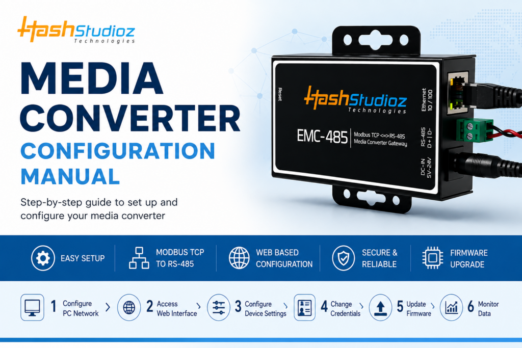
This manual provides a step-by-step guide for setting up and configuring your media converter device.
1. Initial Setup and Hardware Connection
Before accessing the configuration interface, ensure your hardware is properly connected and your computer is on the same network.
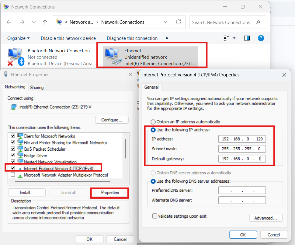
- Step 1: PC IP Configuration: Configure your laptop or PC’s IP address to be on the same subnet as the device.
- IP Address: 192.168.0.129
- Subnet Mask: 255.255.255.0
- Default Gateway: 192.168.0.1
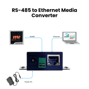
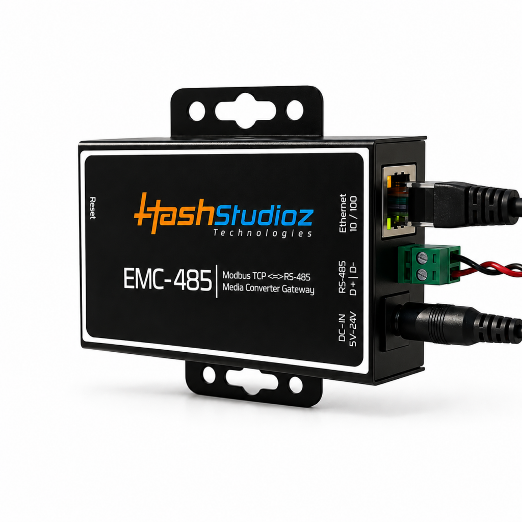
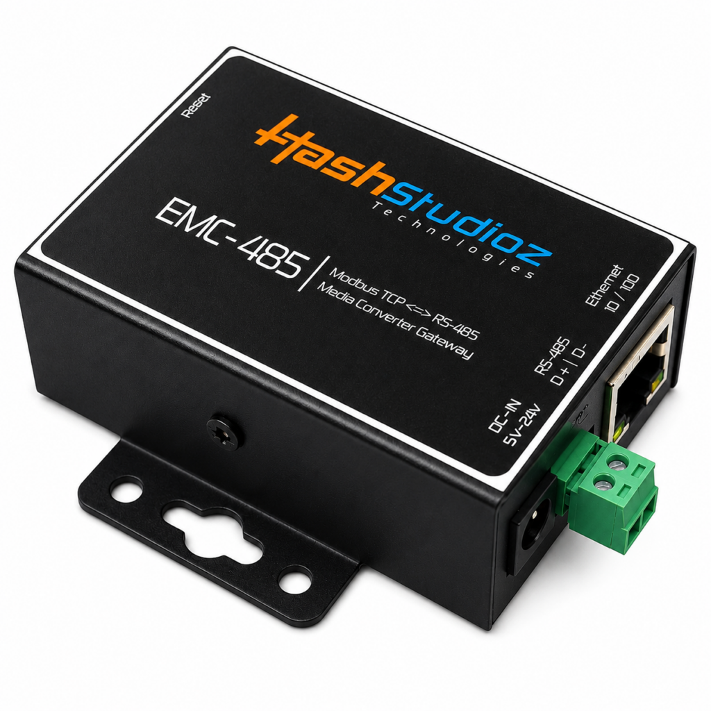
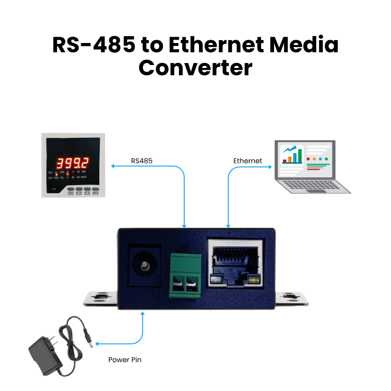
- Step 2: Physical Connection: Connect the media converter’s Ethernet port to your PC and plug in the 12V DC Power supply.
- LED Indicators: Look for a solid orange LED and a blinking green LED on the Ethernet port to confirm the connection is active.
2. Accessing the Web Configuration Interface
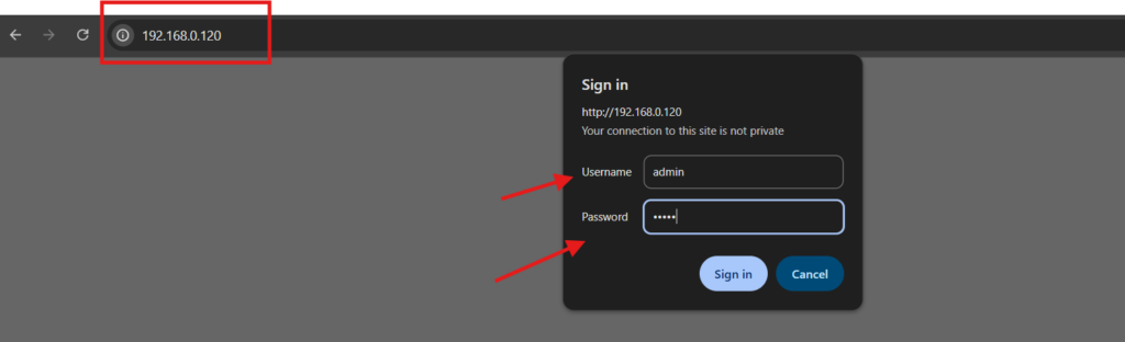
- Step 3: Login: Open a web browser and enter the default IP: 192.168.0.120.
- Default Username: admin
- Default Password: admin
3. Device Configuration Tabs
Once logged in, you can navigate through the following tabs to manage the device:
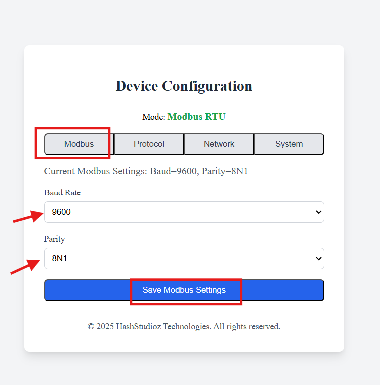
Modbus Tab (Serial Parameters)
This tab is used to configure serial communication details.
- Baud Rate: Supports 9600, 19200, 38400, and 115200.
- Parity/Data/Stop Bits: Options include 8N1, 8E1, and 8O1.
- Action: Click “Save Modbus Settings” for changes to take effect immediately.
Note: If you need any other baud rates or Parity, it can be done through the OTA process, Contact our support team for this.
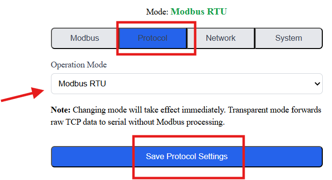
Protocol Tab (Working Mode)
Define how the device handles data transmission.
- Modbus RTU (Server Mode): Converts Modbus TCP data from the Ethernet port into Modbus RTU data for the RS485 port using a poll-and-response mechanism.
- Transparent Mode: Forwards raw TCP data (Hex or ASCII) directly to the serial port without processing. It also works on Poll and response mode.
- Action: Click “Save Protocol Settings”.
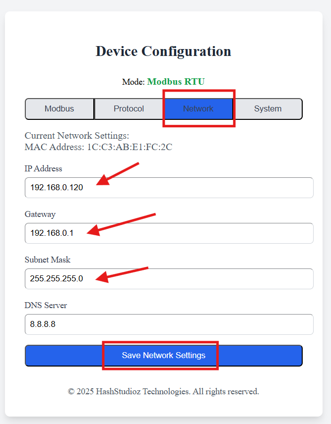
Network Tab (IP Configuration)
Used to change the device’s network identity.
- Parameters: Set a new IP Address, Gateway, and Subnet Mask. (DNS Server is optional.)
- Requirement: A reboot is required to save and initialize the new IP settings. After rebooting, you must use the newly assigned IP address to access the web UI. You can reboot the device from the System tab or simply disconnect the power and reconnect it again.
Note: After rebooting, you must use the newly assigned IP address to access the web UI.
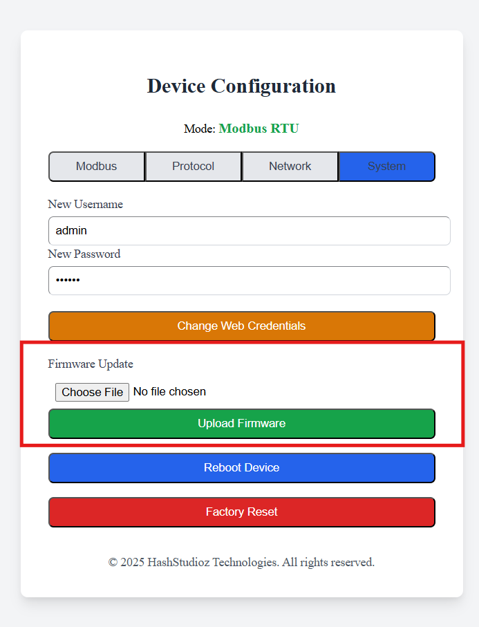
System Tab (Maintenance)
Manage the device’s security and firmware.
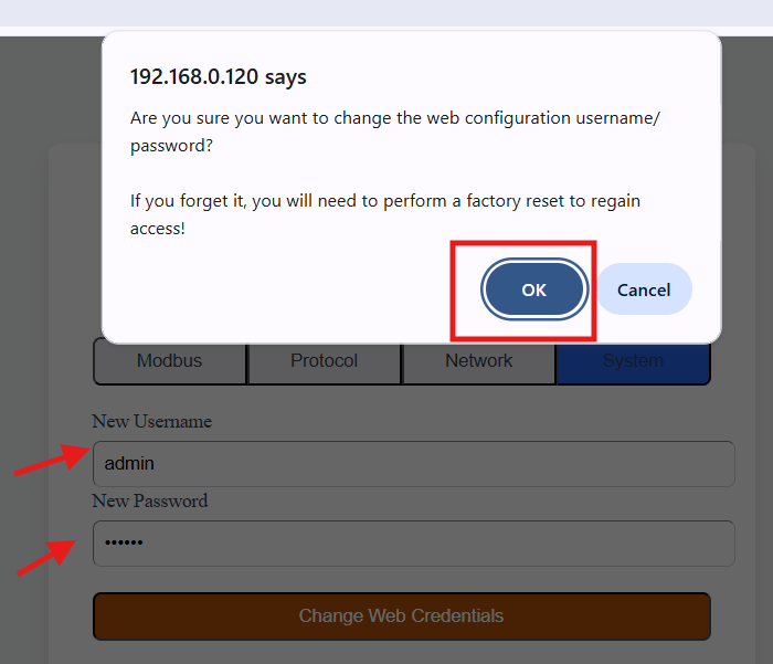
- Change Credentials: Enter a new username and password, then click “Change Web Credentials” and confirm with “OK”.
- Firmware Update: Upload authorized firmware files to fix bugs or enhance features. Do not upload unauthorized firmware as it can brick the device.
- Reboot Device: Restart the device through the web UI.
- Factory Reset: Reset the device to its default state (192.168.0.120). This can be done via the UI or by holding the physical Reset button on the device for 7-8 seconds.
4. Data Communication Setup
To read data from a sensor, PLC, or machine:
- Physical Wiring: Connect the RS485 lines. Connect Device A (D+) to Sensor A and Device B (D-) to Sensor B.
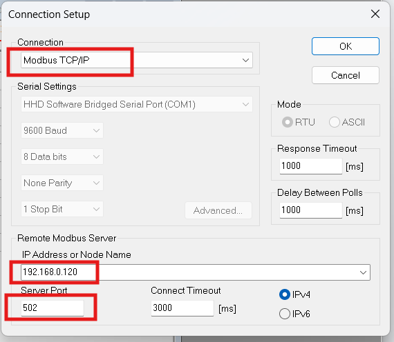
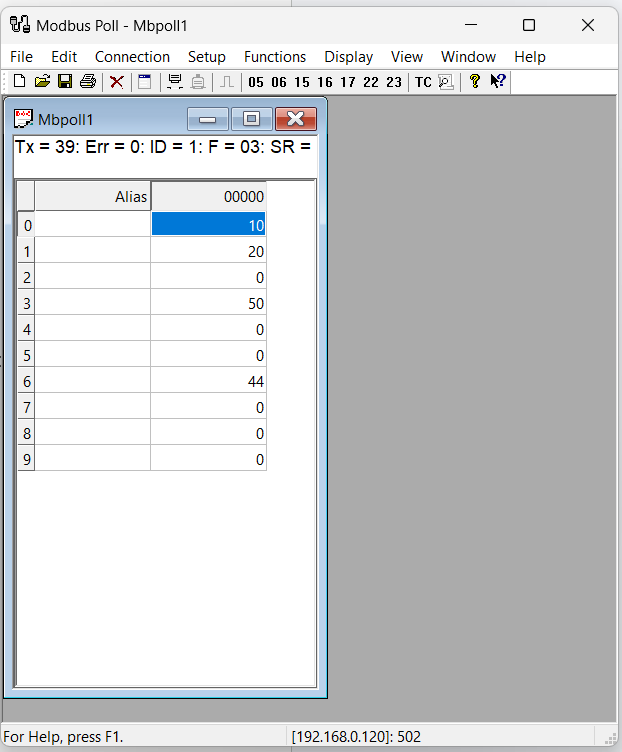
- Software Configuration: Use Modbus software (e.g., Modscan or Modbus Poll) and initiate a TCP connection with these details:
- IP Address: 192.168.0.120 (or your configured IP)
- Server Port: 502 (Fixed and cannot be changed)
- Monitor Data: Once connected, the software will begin polling and displaying data for your Modbus registers.
Looking for More Devices?
Purchase additional Media Converters and networking accessories directly from our store.
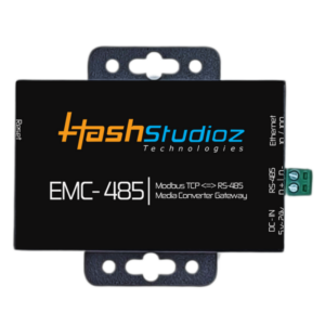
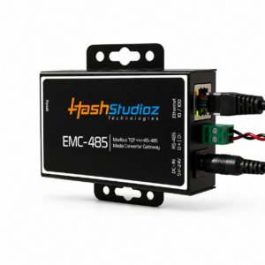
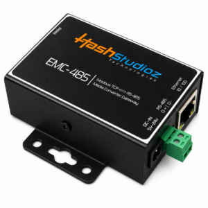
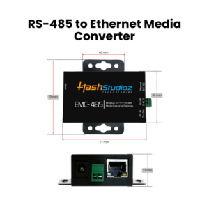

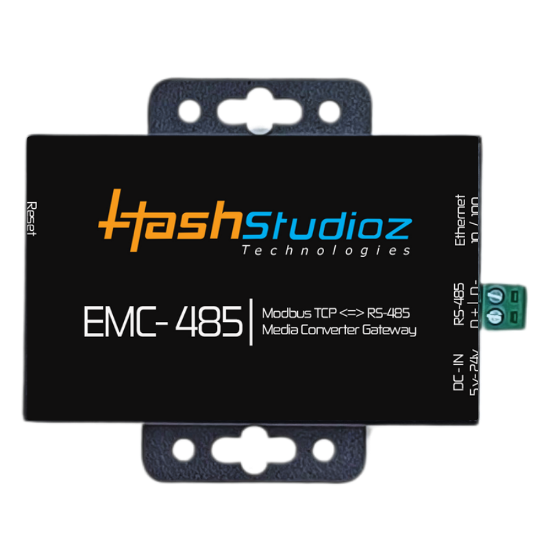

RS-485 to Ethernet Converter – India’s Most Affordable, High-Performance Device
- Plug & Play Setup
- Lowest Price in India
- Industrial Grade | -40°C to +85°C
- Made in India, Built for Industry
- Connect Legacy RS485 Devices to Ethernet